The wiring in your home can be compared to the nervous system in a human body, without it the automation system can neither sense nor act. Whilst nature has perfected its signalling system over thousands of years, home automation has only been around for a few decades. No one knows where this journey is taking us and there will be lots of new switches, sensors, light-fittings and much more to come.
It is therefore important to think ahead and future proof your installation. The wiring is the backbone of an automation system and whilst it is easy to replace a motion sensor, a switch or a light fitting it is much harder to replace the cables that are plastered into your walls.
We therefore recommend that you use cables that have stood the test of time and have become industry standards. In general there are 4 main types of cable that are used for a Loxone system:
- Tree Cable
- CAT7
- Mains Cable
- Speaker Cable
For the sensor side, which is low voltage we recommend you use CAT7 cable. A CAT7 cable can be used for various applications, Tree communications, PC Networks, volt free contacts, serial communication, bus systems, and more. Please note that it cannot be used for 230V loads! For load switching you will have to use appropriately rated power cables, i.e. 1.5mm, 2.5mm, Twin & Earth etc.
WIRING TOPOLOGY
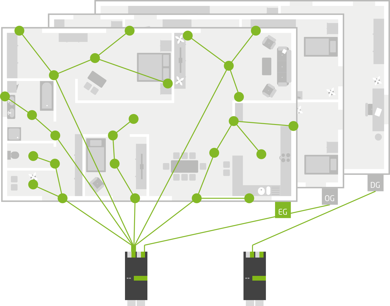
Typically on a Loxone system there is a centrally mounted “panel” that contains all of the Loxone equipment as such this becomes the hub (or node 0) of the installation.
Outputs such as lighting circuits and control for blinds are centrally wired in a STAR pattern where each device has it’s own cable coming back to the central location.
When considering sensors and switches (and indeed heating actuators) these can be wired using the Loxone Tree technology in tandem with the Tree cable. This enables the wiring to be done in a much more efficient and flexible way. In essence, any Tree device can be connected to any other in order to get its control and communication. If this Tree “network” is at some point connected back to the Tree Extension ALL Tree devices will then be connected. This can reduce cabling up o 80% over traditional STAR wired systems and gives huge flexibility in upgrading and updating in the future. True future-proof wiring for the Smart Home. In the below diagrams you can see some examples of wiring Loxone Tree.
IMPORTANT FACTS:
- Wire back to a central point for non-Tree products.
- If you use multiple panels and as such have many Extensions around the project, then the maximum allowable length of the Loxone Link is 500m from the Miniserver to the last extension.
- The Loxone link MUST be a BUS strictly wired from one device to the next.
- The Link has to be terminated at the last device with a 120 Ohm resistor if no Extensions are used then no resistor should be used
- The Link must be a single twisted pair. Our recommendation is a pair of a CAT7 cable between panels and a twisted pair of panel wire within the cabinet.
- The maximum number of Extension on the Loxone Link is 30.
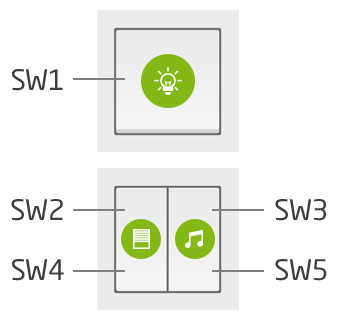
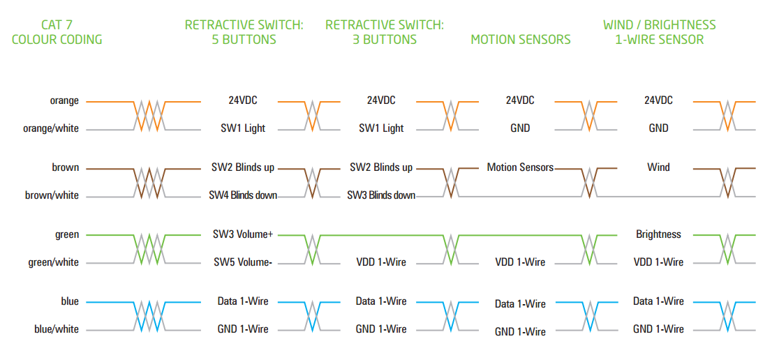
Alongside the Loxone Touch and Touch Pure switches you can also make any conventional switches become much more useful and multi-functional. As long as the switch provides a contact closure it can be wired into the system and then in software can have as many functions as you want it to. We recommend using retractive switches due to the ability to cycle through clicks, double click etc.
CABINET LAYOUT
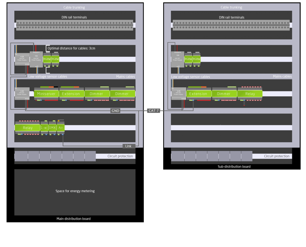
In the diagram below you can see how you can optimally arrange a mains distribution board and a sub-distribution board. In each cabinet there are separate power supplies for the Loxone equipment. We also recommend using additional power supplies for sensors such as presence detectors, as well as for powering LED tape. This is to improve the reliability of your system.
Please note that all power supplies for the Loxone equipment must have their GNDs commoned. To do this you can use spare pairs in the CAT cable for the Loxone Link between the two boards.
To prevent wiring clutter we recommend that you use DIN rail terminals for the wiring of all inputs and outputs. Make sure to plan some spare inputs and outputs as it is easy to miss something at this stage. So the wiring is neat we also recommend using cable trunking. You can see this in the diagram around the outside of the cabinet. Sensors have been wired down the left hand side, and mains cable down the right hand side. To allow this to work, there should be a distance of about 3cm between the extension terminals and the cable trunking.
When connecting the Loxone link and other data connections you should use a twisted pair of your panel wire.
Example of colour wiring:
Orange / White for the power supply
Blue / White for the Loxone Link
Green / White for Loxone Tree
Make sure to use a cabinet large enough to hold all the equipment with space to spare for future expansion. Future Automation has designed a range of cabinets specifically for Loxone hardware, you can view their range of Loxone products here.
SWITCHES
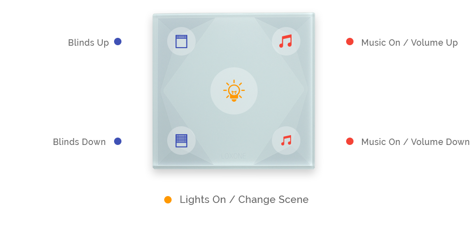
At Loxone we’ve provided some peripheral devices to make product selection even easier. For switches, there is both the Touch and Touch Pure range that comes in both wired and wireless versions. They allow for easy control of the key smart home functions. In addition, they supply temperature and humidity sensing.
With Loxone you can make any conventional switches become much more useful and multi-functional. As long as the switch provides a contact closure it can be wired into the system and then in software can have as many functions as you want it to. We recommend using retractive switches due to the ability to cycle through clicks, double click etc.
WIRING WITH CAT7 CABLES
Why CAT7?
It’s not about data rate. Although this is a fantastic feature and gives us plenty of room for expansion in the future it is not the primary reason for using CAT7. We reccomend using CAT7 for all data communications in a Loxone smart home due to shielding.
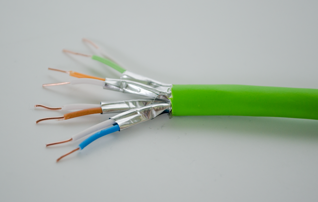
In addition to the external braid commonly found on CAT6 cables a CAT7 also has individually shielded pairs, this allows us to run different data and power signals down different pairs with minimal interference that is not possible with other cables. This also has the added benefit of any times where Electromagnetic Interference (EMI) is particularly high the additional means there is more protection against this affecting the data signals contained within.
In addition to this shielding and the high data rates with an AWG23 core thickness, it is possible to power devices off this cable over much greater distances without suffering from excessive volt-drop.
In essence, all Loxone systems should use CAT7 for maximum functionality and to be future-ready.
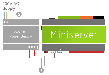
CONNECTING THE MINISERVER TO A POWER SUPPLY
WIRING OF THE MINISERVER
This video shows you how to quickly and easily wire the Loxone Miniserver and an Extension. We take you through the whole wiring process from boxed to powered up!
- Connect the DC output of the 24V power supply to the power terminals on the Miniserver.
- Connect the 24V power supply to the mains only once you have finished the rest of the installation.
Whenever work is done on the cabling of the Miniserver please ensure that power to the Miniserver is removed. Damaged components can occur if this is not observed.
CONNECTING THE MINISERVER TO SEVERAL POWER SUPPLIES
Wiring example for connecting the Miniserver to several power supplies.
You must connect all the power supply GND’s together. Otherwise problems may occur due to difference in potential.
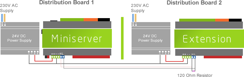
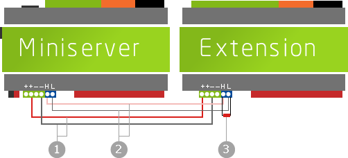
CONNECTING ONE OR MORE EXTENSIONS TO THE MINISERVER
- Connect the power terminals of the Miniserver to the power terminals on the Extensions.
- Connect the Loxone Link connector of the Miniserver with the Loxone Link connector of the Extension.
- Terminate the Loxone Link at the last Extension with a 120 Ohm resistor (comes with your Miniserver package).
Note: If no Extension is connected there is no need to use a 120 Ohm resistor.
CONNECTING ONE OR MORE EXTENSIONS TO THE MINISERVER GO
- Connect the Ground terminal of the Miniserver Go to the power terminals on the Extensions.
- Connect the Loxone Link connector of the Miniserver Go with the Loxone Link connector of the Extension.
- Terminate the Loxone Link at the last Extension with a 120 Ohm resistor (comes with your Miniserver package).
Note: If no Extension is connected there is no need to use a 120 Ohm resistor.
The power should be removed whenever working on the installation, but that if this is not possible then ensure that the blue Link connector is always unplugged before the power connector to prevent damage to the communication circuitry.
via https://www.AiUpNow.com
October 6, 2021 at 05:25AM by IoT Now Magazine, Khareem Sudlow
